Table of Contents
Smart Bootloader (Version 4)
Definition of terms
- Application The microcontroller application to run on top of the bootloader
- TFTP Trivial File Transfer Protocol, an easy protocol for uploading files to a server.
- Smart bootloader A kind of bootloader but a bit more. We call it the BIOS of the Netzer.
- XTEA The encryption algorithm what is used within the smart bootloader.
Abstract
As base the Microchip Bootloader (“Version 2”) was taken. But the bootloader has grown to fully independent project, now - special tailored for the Netzer platform.
The Smart bootloader has the official term “Version 4” and brings a more complete and advanced feature set:
- XTEA cyphering of images ensures ownership and integrity of the image to flash
- Encoded images can not be easily disassembled
- Faulty save flashing of images (CRC-32 valid)
- Eats only 6K of ROM
- Image can consist of many data chunks which can start at different addresses
- Only addresses which are written are erased before
- Jump table enables the application to use some of already implemented functions in bootloader
Structure
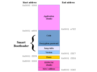
 Fig. 1:
The whole address region of Netzer with all address positions of the bootloader and the installable application.
The virtual address regions are shown in figure 1. The application space is 122 kiB and the bootloader is 6 kiB in size.
The application space consists of one ore more application chunks (see below).
The fuses section is fixed and can not change during application uploads. For that reason we have created special bootloader upgrade applications which can also alter fuse settings.
The special EEPROM space is 256 bytes in size, but only 192 bytes are writable. It is not a true section within the Netzer microcontroller but the external EEPROM mapped within this area. During application uploads it is possible to upload also some EEPROM chunks. Hence it is possible to add some customized configuration to an application.
The Netzer MAC address (6 bytes) is part of the EEPROM space but lives in the bottom of the EEPROM space which is not writable.
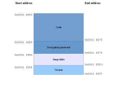
 Fig. 2:
The detailed structure of the bootloader and its addresses.
figure 2 shows the structure of the smart bootloader. The code handles the TFTP traffic between the implemented server and a client running on the PC. Currently only uploads are supported. It also implements routines for accessing EEPROM, Flash, PHY and MAC module and some helper functions. These function are callable from application via the jump table, too. The decryption password is a preprocessed key for the XTEA encrypted application chunks. Last but not least the version field stores the current bootloaders version (currently 4).
Uploading chunks
The Netzer bootloader can be reached via IP address 192.168.97.60 (MAC address 00-04-A3-00-00-00). Data chunks (application and eeprom) are transfered from a TFTP client (tftp, curl, etc.) running on a PC in the same network as Netzer.
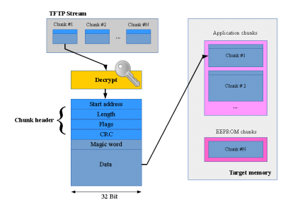
 Fig. 3:
Uploading chunks mechanism.
In figure 3 such a TFTP stream is shown, as they arrive in the bootloader. In the stream there can be a lot of small chunks. The chunks are decrypted (if decryption is enabled) on the fly.
All chunks have a unique header structure.
The bootloader code checks this header what to do next. The Start address and Length fields give the position within the Netzer address space. With this knowledge the bootloader checks whether the chunk fits. The data length must be 8 byte aligned.
Flash chunks are handled extra:
- Old chunks are always erased completly, even if only parts are affected.
- Only if there are already chunks stored in target address space, the flash is erased.
- Chunks must start at a flash erase page (1024 byte aligned)
The Flags field is currently not used and always zero.
The CRC field is the CRC-32 over the whole chunk data (Magic word + data). It is used to ensure image consistency. The CRC check is always done after the chunk was written to flash/EEPROM.
The magic word (0xF0F4EF00) must always be the first data within a data chunk. It ensures a jump to the bootloader code which is located at 0x1e800.
Building the bootloader
The code was entirely written in Assembler (can be assembled with GPASM or MPASM). Only some small pieces of code are in C and must be compiled with the latest MCC18 compiler from Microchip.

