Table of Contents
Impulse handling with Netzer IO
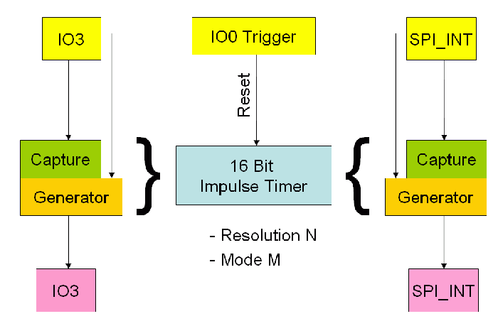
Netzer is able to generate and capture signals at IO3 and SPI_INT.
The image shows the structure of the impulse generator/capture.
The impulse module is divided into two modes, the unsynchronized mode and the IO0 synchronized mode. Both, IO3 and SPI_INT, can either work in unsynchronized or in IO0 synchronized mode.
Furthermore a mode M can be configured:
- Continuous mode
- Single
- Triggered by IO0
Resolution N can be either 100ns, 200ns, 400ns or 800ns. All raw values associated with Capture/Generator module must be multiplied by N to get the final time value.
Last but not least channels can be configured for capturing (measuring impulses) or generating impulses.
Examples
Some of the examples below show both signals IO3 and SPI_INT. Of course impulse module can be configured to use only one of them.
The examples below only show positive logic. Simply invert the signals to get negative logic examples.
In the IO0 examples the IO0 trigger is configured for rising edge. Simply invert the IO0 signal to get falling edge examples.
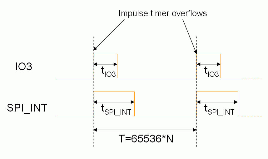
Generating impulses in continuous mode (Unsynchronized)
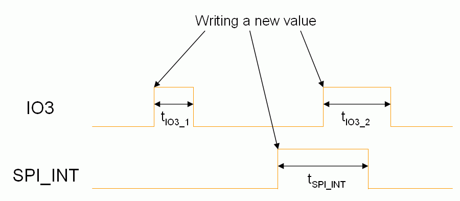
Generating impulses in single mode (Unsynchronized)
Generating impulses in "Triggered by IO0" mode (Unsynchronized)
This mode shall not be used.
Generating impulses in continuous mode (IO0 synchronized)
This mode shall not be used.
Generating impulses in single mode (IO0 synchronized)
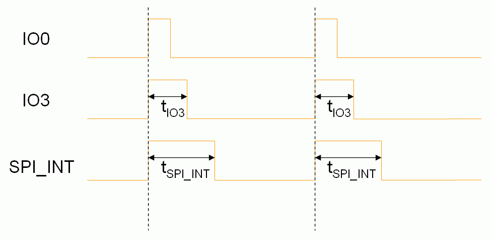
Generating impulses in "Triggered by IO0" mode (IO0 synchronized)
Measuring impulses in continuous mode (Unsynchronized)
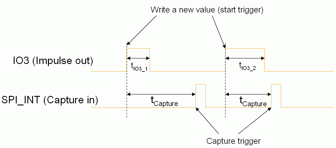
Measuring impulses in single mode (Unsynchronized)
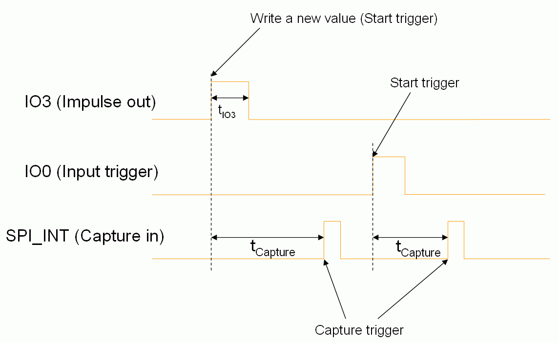
Measuring impulses in "Triggered by IO0" mode (Unsynchronized)
This mode shall not be used.
Measuring impulses in continuous mode (IO0 synchronized)
This mode shall not be used.
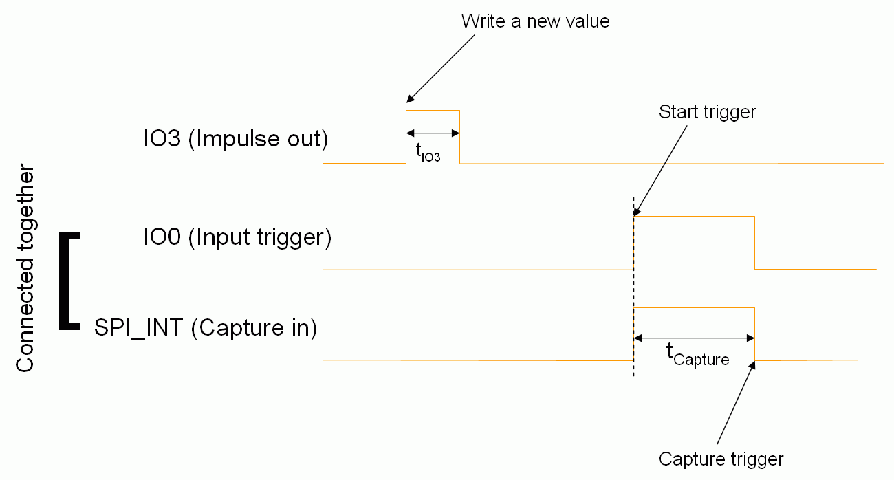
Measuring impulses in single mode (IO0 synchronized)
The second example shows the special case of an ultrasonic sensor like HC-SR04. This sensor needs a 10 µs impulse at the TRIG input which shall be connected to IO3. The pulse length of sensor singnal ECHO decodes the distance to the detected object. The signal must be connected to IO0 and SPI_INT. IO0 must be configured for rising trigger edge, SPI_INT for falling capture edge.
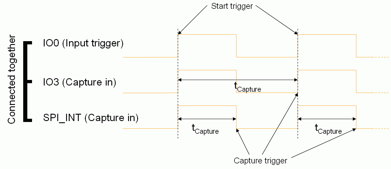
Measuring impulses in „Triggered by IO0“ mode (IO0 synchronized)
In this mode the periode of periodic signals or pulse length can be measured. Connect the signal to measure to IO0 and IO3 or SPI_INT or both. For period length the IO0 trigger edge and the capture edge must be equal (like IO3 in image below). For positive pulses the IO0 trigger edge must be rising, the capture edge falling edge (like SPI_INT in image below). For negative pulses the IO0 trigger edge must be falling, the capture edge rising edge.
