Table of Contents
SPI Master Ethernet Gateway
In this mode the Ethernet gateway Netzer can directly communicate with SPI devices like memories or LCDs.
One or more slaves are connected to Netzers SPI interface (3 wire). The Netzer acts as SPI master.
SPI normally needs one chip select per slave. Sometimes more wires are necessary in order to control a slave. For example a reset signal.
But also shift register circuit is possible. In this case the slaves are cascaded in a long chain one after another. The advantage of this practice is that all slaves share one chip select wire. Sometimes even none is needed. A typical example for chaining slaves would be the 8 bit wide shift register 74×594, which can be chained in any order.
Settings at the web interface
The SPI master mode is activated at the common settings page.
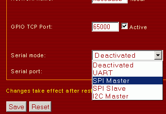
Do not forget to restart after changing the mode!
For TCP connections the serial server port is used.
Furthermore the SPI settings are made at the serial settings page.

The following frequencies can be set for SPI_CLK:
| Frequency | Since firmware version |
|---|---|
| 10,4 MBit/s (Wow!) | 1.0 |
| 2,6 MBit/s | 1.0 |
| 650 kBit/s | 1.0 |
| 100 kBit/s | 1.5 |
| 50 kBit/s | 1.5 |
| 10 kBit/s | 1.5 |
| 5 kBit/s | 1.5 |
| 1,3 kBit/s | 1.5 |
For SPI also the clock mode is important. The polarity of the clock signal and the takeover edge are determined like:
| Modus | Silent state of the clock signal | Takeover edge |
|---|---|---|
| Modus 0 | 0 | Rising |
| Modus 1 | 0 | Falling |
| Modus 2 | 1 | Falling |
| Modus 3 | 1 | Rising |
The figure shows all settings at a glance in a time diagram:

Communication
Since a connection is established, the SPI Master can be used. All received characters from TCP Client but the backslash '\' (Escape) are transparently sent from Netzer to the SPI master module. Escaped characters, which are not supported due to the installed firmware version are also transparently conveyed. For a complete listing of the supported escape sequencies see below. The ring buffer has a size of 256 byte for buffering transmission bursts.
The SPI Master module generates for each byte eight clock edges at SPI_CLK and shifts out the data at SPI_MO. At the same time the slave delivers data at SPI_MI (see figure above). The so received byte is sent automatically on the TCP connection. In this direction no escaping is used.
Firmware Base version

With the free downloadable base version exactly one slave is supported. Also chaining of more slaves is supported because therefore only vxcyone chip select is needed. The example circuit like the figure above consists of the four pins SPI_MI, SPI_MO, SPI_CLK and SPI_CS. SPI_MO is the data output (data from Netzer to slave). SPI_MI ist the data input (data from Slave to Netzer). The clock signal (SPI_CLK) is controled by Netzer.
SPI_CS synchronizes the access and selects the slave - in case data is transmitted, Netzer automatically resets the signal to 0. Setting the chip select to 1 can be done through a special escape sequence: (0x5C 0x00).
All other GPIO pins of the Netzer are free usable and controllable via the web interface or the GPIO server.
Supported escape sequencies in the base version:
| Sequence (in hex) | Meaning |
|---|---|
| 0x00 | SPI_CS is set to 1 - the current slave session will be finished. |
| All others | Character is transparently transmitted. |
Firmware pro version

In contrast to the base version the pro version uses no dedicated chip select signal. But there exist special escape sequencies for accessing all the pins of Netzer which are configured as digital outputs. Thereby up to 10 different slaves can be selected. Also other control pins can be serviced which are sometimes needed by special SPI modules. All Netzer GPIO pins but SPI_CLK, SPI_MO and SPI_MI are free usable and controllable via the web interface or the GPIO server.
Also the SPI mode can be dynamically configured. Furthermore wait states can be added, i.e. to accomplish dedicated setup/hold times of slaves.
To avoid blocking the Netzer firmware all received escape sequencies are processed sequential. I.e. between the processing of the escapes smaller or greater brakes are made. This can lead to a small jitter of the sequencies. Therefore for fixed times the wait states should be used.
Supported escape sequencies in the pro version:
| Sequence (in ASCII) | Sequence (in hex) | Meaning | Since firmware version |
|---|---|---|---|
| 0 | 0x30 | SPI-Mode 0 will be activated. | 1.5 |
| 1 | 0x31 | SPI-Mode 1 will be activated. | 1.5 |
| 2 | 0x32 | SPI-Mode 2 will be activated. | 1.5 |
| 3 | 0x33 | SPI-Mode 3 will be activated. | 1.5 |
| a | 0x61 | Set Pin IO0 to 0. | 1.4 |
| b | 0x62 | Set Pin IO1 to 0. | 1.4 |
| c | 0x63 | Set Pin IO2 to 0. | 1.4 |
| d | 0x64 | Set Pin IO3 to 0. | 1.4 |
| e | 0x65 | Set Pin IO4 to 0. | 1.4 |
| f | 0x66 | Set Pin IO5 to 0. | 1.4 |
| g | 0x67 | Set Pin TX to 0. | 1.4 |
| h | 0x68 | Set Pin RX to 0. | 1.4 |
| i | 0x69 | Set Pin SPI_CS to 0. | 1.4 |
| j | 0x6A | Set Pin SPI_INT to 0. | 1.4 |
| A | 0x41 | Set Pin IO0 to 1. | 1.4 |
| B | 0x42 | Set Pin IO1 to 1. | 1.4 |
| C | 0x43 | Set Pin IO2 to 1. | 1.4 |
| D | 0x44 | Set Pin IO3 to 1. | 1.4 |
| E | 0x45 | Set Pin IO4 to 1. | 1.4 |
| F | 0x46 | Set Pin IO5 to 1. | 1.4 |
| G | 0x47 | Set Pin TX to 1. | 1.4 |
| H | 0x48 | Set Pin RX to 1. | 1.4 |
| I | 0x49 | Set Pin SPI_CS to 1. | 1.4 |
| J | 0x4A | Set Pin SPI_INT to 1. | 1.4 |
| t | 0x74 | Wait 100 µs till processing of the next character. | 1.5 |
| T | 0x54 | Wait 1 ms till processing of the next character. | 1.5 |
| All others | Character is transparently transmitted. |
SPI master in single slave operation
For using this SPI master in a single slave environment this example is provided here. We assume that the slave is connected with the SPI_CS wire like shown below.

The SPI_CS shall be low active - a low level selects the slave. The pull up resistor at CS is needed to prevent false selection. This may occur on power up if CS is not driven by Netzer. The pull up resistor at SPI_MI is needed to prevent floating in case the slave is not selected and therefore the pin is not driven.
The data string
01 23 45 67 89
shall be sent to the SPI slave.
The command for controlling the SPI_CS line is an escape sequence consisting of two bytes:
5c 69
for setting SPI_CS to low and
5c 49
for setting SPI_CS to high.
The final code together:
5c 69 01 23 45 67 89 5c 49


