Table of Contents
Netzer pin map
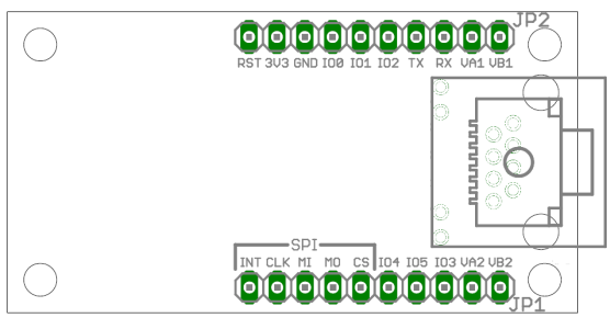
Pins of pin header JP1
| Name | Description |
|---|---|
| INT | GPIO pins |
| CLK | |
| MI | |
| MO | |
| CS | |
| IO4 | |
| IO5 | |
| IO3 | |
| VA2 | Connection for Power-over-Ethernet. That is the center tap of the Ethernet coil between RJ45 pins 3 and 6. |
| VB2 | Connection for Power-over-Ethernet. This pin is directly connected to the network jack of Netzer (RJ45 pins 7 and 8). |
Pins of pin header JP2
| Name | Description |
|---|---|
| RST | Use this pin to reset Netzer. The signal is low active (this means 0 resets Netzer). The Reset signal can also be used for waking up Netzer from sleep mode (after shut down). The pin is optional and can be left open. |
| 3V3 | Pin for power supply. Minimum voltage is 3.1 V. Maximum voltage is 3.6 V. |
| GND | Ground potential. |
| IO0 | GPIO pins |
| IO1 | |
| IO2 | |
| TX | |
| RX | |
| VA1 | Connection for Power-over-Ethernet. That is the center tap of the ethernet coil between RJ45 pins 1 and 2. |
| VB1 | Connection for Power-over-Ethernet. This pin is directly connected to the network jack of Netzer (RJ45 pins 4 and 5). |
Power-over-Ethernet (PoE)
The four connections VA1, VA2, VB1 and VB2 are connections from the network socket where a Power-over-Ethernet supply can be connected to.

The image shows an example circuit. Here the PoE supply AG9033 of Silver Telecom is used.
Overview over all GPIO signals
Here only some common informations are shown. The implemented functionality of a single IO depends on the single project.
| Netzer Name | ID | PIC Pin | Maximum output current | Maximum input voltage | Functionality |
|---|---|---|---|---|---|
| SPI_INT | j | RC2 | 25 mA | 5,5 V | Interrupt pin of the SPI slave module, PWM capable |
| SPI_CLK | k | RC3 | 25 mA | 5,5 V | Clock line of the SPI module or I2C module |
| SPI_MI | l | RC4 | 25 mA | 5,5 V | Data input of the SPI module, data line of the I2C module |
| SPI_MO | m | RC5 | 25 mA | 5,5 V | Data output of the SPI module |
| SPI_CS | i | RF7 | 2 mA | 5,5 V | Select input of the SPI slave module |
| RX | h | RC7 | 25 mA | 5,5 V | UART Receive line |
| TX | g | RC6 | 25 mA | 5,5 V | UART Send line |
| IO0 | a | RB0 | 25 mA | 5,5 V | Interrupt capable input |
| IO1 | b | RB1 | 25 mA | 5,5 V | Interrupt capable input |
| IO2 | c | RB2 | 25 mA | 5,5 V | Interrupt capable input |
| IO3 | d | RD1 | 8 mA | 5,5 V | PWM capable |
| IO4 | e | RA2 | 2 mA | 3,3 V | ADC capable |
| IO5 | f | RA3 | 2 mA | 3,3 V | ADC capable |


